What it does
The loop closes at step 05 → step 01. The verifier is shown the instruction and the image, and nothing else.
The design rule for the whole project was modular pipeline first, learning second: build a fully engineered system that works and can be measured, then run a small learned-policy experiment against it. That ordering means there is a working fallback at every stage, and the learned policy has an honest baseline to be compared to rather than being graded on its own.
The pipeline may never read object positions out of the simulator. Perception, reasoning and motion see rendered images and the robot’s own joint angles — nothing else. Ground truth is used only to score episodes and to draw clearly-labelled debug overlays. A pytest case scans the pipeline packages on every run and fails the build if any of them import the ground-truth module or read an object pose directly.
Demo
The self-correction, on its own
Results
Baseline — 20 seeded scenes × 5 instruction templates
| Instruction template | n | Success |
|---|---|---|
| pick up the X block | 20 | 100% |
| put X to the left/right of Y | 20 | 100% |
| put X in front of / behind Y | 20 | 100% |
| stack X on top of Y | 20 | 100% |
| put X between Y and Z | 17 | 94.1% |
| overall | 97 | 99.0% |
99% on 97 episodes is one failure. One failure is not a failure distribution — it cannot tell you which stage is fragile or where the system’s operating envelope ends. So the baseline is reported as-is and the actual work is the stress sweep below, which degrades conditions until things break and reports the curve.
Stress sweep — 679 episodes across seven conditions
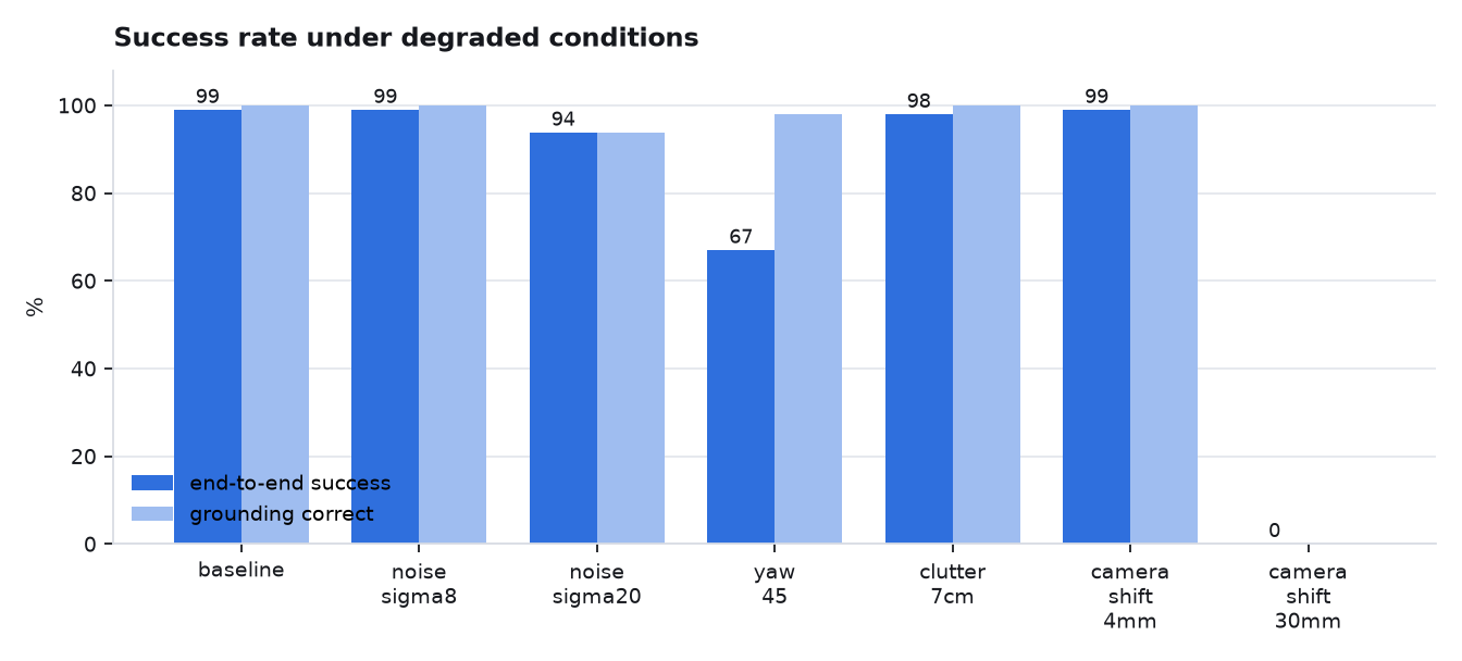
| Condition | End-to-end | Grounding | What it probes |
|---|---|---|---|
| baseline | 99.0% | 100% | — |
| sensor noise σ=8 | 99.0% | 100% | mild camera noise |
| sensor noise σ=20 | 93.8% | 93.8% | the palette’s weakest colour pair |
| block yaw ±45° | 67.0% | 97.9% | the fixed-yaw grasp assumption |
| clutter, 7 cm spacing | 97.9% | 100% | clearance search, occlusion |
| stale calibration, 4 mm | 99.0% | 100% | error below the guard threshold |
| stale calibration, 30 mm | refused | — | the startup guard fires on all 97 |
Excluding the 97 episodes the calibration guard refused up front, 582 episodes were attempted and 92.6% succeeded. The guard declining to drive a robot it knows is miscalibrated is correct behaviour, not a failure, so it is counted separately — folding 97 safety refusals into the taxonomy would bury every real failure underneath them.
Failure taxonomy
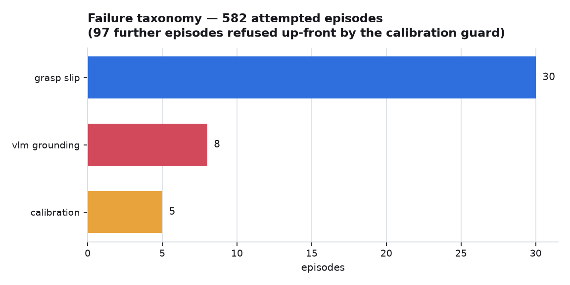
Grasp slip dominates (30 of 43 failures), and almost all of it is the ±45° yaw condition. The gripper approaches at a fixed yaw, so a block rotated 45° presents a corner to the finger pads instead of a face; the pads close on an edge and the block is dropped in transit. That is the limitation the project documented in week one — and the number that makes it real, rather than an assertion, is 67%.
Grounding failures were predicted before they happened. A colour calibration early on measured the rendered hue of every block material and found orange and yellow separated by 10 units out of 180 — the tightest pair in the palette. Under σ=20 noise, 5 of the 8 grounding failures involve orange. They also fail safely: the perceiver reports “multiple candidates” and declines rather than moving the wrong block.
Per-stage conditional success
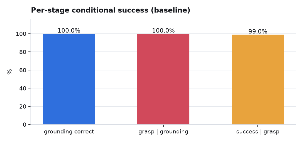
An end-to-end number is a product of stages, so it hides which stage carries the risk. The conditional decomposition says grounding is not the bottleneck at baseline (100%), nor is the grasp given correct grounding (100%), and the residual sits downstream of a successful grasp. Under stress the picture inverts: grounding falls to 93.8% and drags everything after it. One aggregate number would have shown 92.6% and pointed nowhere.
Verifier reliability
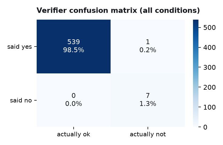
The verifier scores almost perfectly. It shouldn’t be believed at face value: the verifier and the grounder share a detector, so when segmentation fails they fail the same way and the verifier never contradicts the grounder about what is on the table. Their errors are correlated by construction. This is the strongest argument in the project for a vision-language verifier — an independent perception path is what makes closed-loop checking worth having. A shared-backbone verifier only re-checks geometry, which is the easy half.
Things that went wrong, and what they taught
The detector was at 85% and every error was the same one
Orange kept reading as yellow. It wasn’t the thresholds: the rendered orange face was RGB (255, 238, 30) — hue 28, against yellow’s 30. Saturated materials under a bright light clip their dominant channel at 255, and the extra light lands in the other channels, sliding the measured hue toward neutral.
The fix was to expose the scene correctly, not to widen the detector’s bins — widening bins would have been tuning the simulator to make my code work. A calibration script now measures each material’s rendered hue at nine workspace positions and places the bin edges at the measured midpoints. Detection went to 100% on 48 blocks.
Every grasp was aiming 7 mm high
Open-loop IK plus a position servo left a repeatable 6.7 mm droop under gravity — finite servo stiffness, exactly what a real position-controlled arm does. The fix is an outer loop on the tool pose: measure where the tip actually ended up from forward kinematics of the measured joint angles, then re-solve for a target shifted by the residual. It uses only the robot’s own state, and converges in one correction because the droop is systematic rather than random. Tracking error went from 6.7 mm to 0.6 mm.
A 99% success rate was propped up by retries
Collecting demonstrations, only 56% of episodes succeeded — against a 99% measured success rate. The telemetry showed grasps that had clearly worked (motor effort 1.9, block held) being reported as failures, because the expected block width was 21% too large.
The cause: block size was estimated from the detection’s bounding box, and an axis-aligned box around a square rotated by θ has side s(|cos θ|+|sin θ|) — at 15°, exactly ×1.22. Switching to √(mask area), which is rotation-invariant, and calibrating out a measured residual bias fixed it. Demonstration yield went 56% → 99% and sweep wall-time dropped from 114 s to 25 s because the retries that had been masking it were no longer needed.
The uncomfortable part is the lesson: the headline number was right and the system underneath it was wrong. Retries were quietly absorbing a systematic defect, and it only surfaced when a different consumer used the same components without them.
The robot retried the identical wrong action three times
The first self-correction run failed with the same grasp error three times at the same coordinate. The diagnosis routed a grasp failure to “retry the grasp”, which never re-examines the coordinate that produced it. The executive now escalates a twice-repeated grasp failure to a perception fault, on the principle that a physical action that fails the same way twice is evidence about its input, not about the action.
Stacking looks like failure from directly overhead
The verifier marked correct stacks as failures: putting one block on another hides the lower one from a top-down camera, and “I can’t see the reference block” was being read as the instruction not being satisfied. It is the opposite — occlusion of the reference with the target present at that spot is the strongest evidence a monocular overhead view can give that the stack happened. The verifier now reasons that way and corroborates with the 45° camera.
How the geometry works
Pixel → world
A camera is specified by a vertical field of view, so focal length in pixels is f = (H/2) / tan(fovy/2) — 659.4 px for the overhead camera at 640×480, giving 1.82 mm per pixel at the table. To locate a block, backproject its pixel into a world ray and intersect the table plane: s = (zplane − oz) / dz.
Both a full camera model and a four-point planar homography were implemented and compared. On table-level points they are numerically identical — two algebraic inversions of the same noiseless projection — so the comparison was decided by something else entirely.
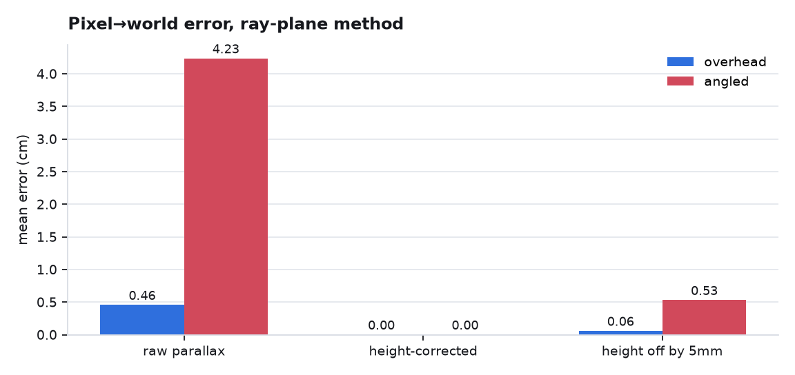
| Mean error, ray–plane method | Overhead | 45° camera |
|---|---|---|
| raw parallax on a 40 mm cube | 0.46 cm | 4.24 cm |
| intersecting at the block’s height | 0.00 cm | 0.00 cm |
| …with the height wrong by 5 mm | 0.06 cm | 0.53 cm |
A detector sees a cube’s top face, not its footprint, so intersecting at z = 0 is wrong by the parallax. Intersecting at the block’s height instead is exact for an upright cube. The decisive row is the last one: block height is estimated, and sensitivity to getting it wrong is tan θ of the viewing ray — about 9° overhead versus 45° for the angled camera, a 9× difference. The overhead camera and the ray–plane method were chosen for that, plus one operational reason: the ray–plane model reads the live camera pose, so a startup check catches a camera that has moved. A cached homography would keep returning confident, wrong numbers — which is exactly what the 30 mm stress condition confirms it does.
Inverse kinematics
Damped least squares, hand-implemented on MuJoCo’s Jacobian: dq = Jᵀ(JJᵀ + λ²I)⁻¹e. In the SVD basis this scales each direction by σ/(σ²+λ²) rather than 1/σ, so near-singular directions are abandoned instead of chased. Converges in 5–10 iterations with sub-millimetre residual across the workspace.
A test that probes with an arbitrary error direction will not find the problem: with the arm fully extended, an arbitrary 1 mm error produces an undamped step only ~3× larger than the damped one, because the well-conditioned directions dominate. Aim the same 1 mm along the smallest left-singular vector and the undamped step exceeds 1 radian while the damped step stays near 10⁻⁴. That asymmetry is why singularity bugs get reported as “intermittent” on real robots — and why the test now probes deliberately.
Learned-policy experiment
With the engineered pipeline measured, the same task was posed as behaviour cloning: 524 demonstrations from the scripted expert, a small MLP predicting which primitive comes next and with what target coordinates. Observations are detected blocks in the table frame plus gripper state — not raw pixels. That is a deliberate narrowing, and it is the honest thing to say about it: this experiment does not learn perception, it learns the policy layer. A pixel-to-action policy would have to learn colour constancy and projective geometry from scratch, which is what makes real VLA work need enormous, diverse data.
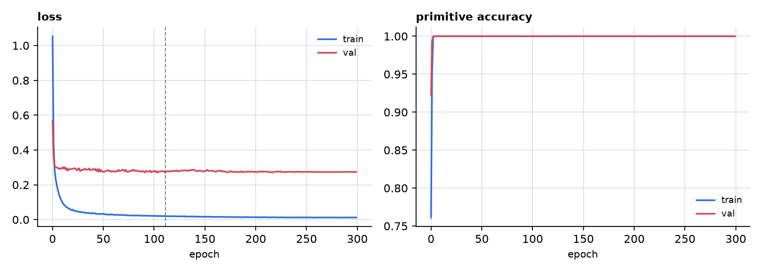
The first encoding could not be learned at all — validation accuracy froze at 46%. The reason was mine, not the model’s: two of the five primitives shared an identical observation while carrying different labels, so the dataset was not a function and no model could fit it. The network was correctly learning the marginal distribution. Re-posing the action space so each observation determines one action fixed it, and moved the interesting question to where it belonged — the placement regression.
It memorises — and more data doesn’t fix it
The policy fits its training scenes to 0.45 cm and generalises at 7.3 cm. Two explanations fit that, and they call for opposite responses: too little data, or the wrong inductive bias. A learning curve tells them apart.
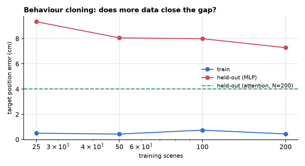
| Training scenes | Rows | Train | Held-out |
|---|---|---|---|
| 25 | 338 | 0.50 cm | 9.33 cm |
| 50 | 667 | 0.43 cm | 8.06 cm |
| 100 | 1,337 | 0.75 cm | 7.99 cm |
| 200 | 2,674 | 0.45 cm | 7.28 cm |
| 200, slot-attention | 2,674 | 0.88 cm | 4.03 cm |
Eight times the data buys 2 cm. The curve flattens well above the training error — the signature of an inductive-bias problem, not a data problem. Swapping the MLP for a model given the shape of the task (score each object slot against the instruction, attend, then predict an offset relative to the attended slot) nearly halves the error at the same data, and on the selection subtask specifically it is 2.9× better: 11.4 cm → 3.9 cm.
That is the concrete, local version of why production VLA systems are large pretrained attention models over tokens rather than small per-task policies. “Find the thing the instruction refers to, then act relative to it” is the operation attention is. An MLP over a flat scene vector has to discover it as an arbitrary function of 45 inputs.
Rolled out closed-loop: 16.7% against the expert’s 100%
| Template | n | Cloned policy | Scripted expert |
|---|---|---|---|
| pick | 20 | 15% | 100% |
| place lateral | 20 | 35% | 100% |
| place depth | 20 | 20% | 100% |
| stack | 20 | 0% | 100% |
| between | 16 | 12.5% | 100% |
| overall | 96 | 16.7% | 100% |
77 of the 80 failures are “grasp failed”. The grasp tolerates about 2 cm of
position error; the policy localises the target block to 11.4 cm. It isn’t
failing at manipulation — it never gets to manipulate. It fails at selection, one
step earlier, and the closed-loop number is just the open-loop error seen through a
threshold. stack at 0% is the sharpest case, because stacking needs the tightest
lateral accuracy of any template.
It is also a clean demonstration of compounding error under distribution shift: the expert only ever demonstrates states along successful trajectories, so once the policy’s first action is 11 cm off, it is in a state the training data never described and has no way back. That is the standard argument for interactive correction, which this experiment does not implement.
Read honestly, 16.7% vs 100% is not “the expert is better at robotics”. The expert has structural access to the answer — it computes reference + 12 cm in a direction resolved from the relation, by an exact geometric rule. The policy has to infer that rule from examples. The engineered version winning is the expected outcome, and precisely why the project was sequenced pipeline-first: it is both the fallback and the yardstick.
Honest limitations
- The vision-language model path is implemented but has never been run. The Anthropic client, strict-JSON schema, single repair re-query, cost accounting and spend caps are all written and unit-tested against a fake transport — but there is no API key on the machine this was built on, so it has not made a live call. Every number on this page is the classical computer-vision perceiver’s, and no VLM accuracy is claimed anywhere in the repository.
- Cubes only, 30–45 mm. A cube’s top-down grasp works at any yaw within 45° of a face, so orientation is bounded rather than estimated. Lifting this means estimating yaw from the mask’s principal axis (already computed) and rotating the wrist.
- Top-down grasps only. Gripper orientation is fixed pointing down with one free yaw, which reduces the IK orientation constraint to one degree of freedom and keeps SO(3) interpolation out of the trajectory layer.
- Straight lines in joint space, no planner. Safe here because every transit happens above a hover height, and wrong the moment something tall stands between two waypoints.
- Collision avoidance only avoids what was detected. A block perception misses is a block the arm will happily place on top of.
- Everything is simulation. No claim is made about sim-to-real transfer. The contact parameters are pinned to a reference scene from MuJoCo Menagerie specifically so that robustness has to come from the system rather than from tuning the physics.